Micro Automata
Materials:
• Wide clean plastic cup or clear solo cup.
• A straw
• Skewers
• Bottle caps
• Foam core
• Tape
Tools:
• Scissors
• Hot glue gun
• A wood screw
• Phillips screw driver or pencil
Automata meaning self operating machine typically consisted of a clockwork statue or scene and were first created centuries ago in Europe and Asia. They were in many ways the direct ancestor of what became electro mechanical robots. For our purposes automata are a good way to explore machine's function of converting one form of energy and motion into another. They are also a way to teach simple mechanical problem solving skills.
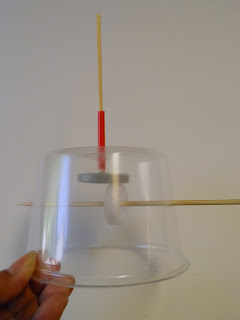
Micro automata were the first in our series of attempts to simplify cardboard automata. The basic idea was to avoid building the box by putting the mechanism inside a clear plastic container. Mechanically they are very simple. They have a input shaft with a crank coming out the side and an output shaft coming out the top with a mechanism in the middle to convert the motion. Here is a good basic model to start from to which more features can be added.
First you use a wood screw to poke a hole in the side your cup about half way down and big enough for your skewer.
Insert the skewer and mark the position of the second hole so the skewer is parallel to the top of the cup. When inserted this skewer is the input shaft.
Make a hole in the center of the bottom of the cup using a wood screw.
Use a phillips screw drive or pencil to widen the hole until a straw will fit tightly in the hole. Note that the straw has to be big enough for your output skewer, so size your straw and hole accordingly. With the straw sticking about 1/2'' into the cup hot glue it in place being careful not to melt it.
Prepare the output shaft, by glueing about a half skewer into a bottle cap (a round piece of foam core or card board works too)
At this point you have to decide what you want your output and whatever you build on it to do. You can either poke a hole in the center or off center in the bottle cap for the input shaft. Making the hole centered will result in a friction gear which will spin the output skewer when the crank is turned. If you put the hole off center you will get a cam and follower, the output skewer will go up and down when the crank is turned.
In this case we went for a friction gear resulting in a spinning output.
Here are the two parts assembled into the cup. Note that you have to put the output skewer in first and then add the input shaft below it.
The final mechanical step is to add a crank and some spacers to keep the input from sliding around, a bottle cap or a foam core square can be used to make the crank. You can use tape flags or cardboard/ foam core washers to keep the crank shaft from sliding in and out too much.
The final and most important step is to use the mechanism to drive a puppet or scene, below are some examples we built:
This version used a simple friction gear to turn a horizontal rotation into a vertical rotation.
This version uses a cam that has been placed on the edge of the follower making the bee go up and down and circle the flower slowly. If the cam were placed in the center of the follower, it would just go up and down.
This version uses two offset cams to get the birds to go up and down and back and forth around the tree.


